RIGHT-TO-REPAIR
SVALT products are made with modular right-to-repair systems and components that use bolted/snapped assemblies to help extend product service life and to help reduce environmental impact. Products with an “x” in the current model name indicate modular exchangeable cooling systems, speed/power controls and fans (older models may have more limited exchangeability). Products ship with the tools required to open, access and disassemble these components for right-to-repair cleaning, serving, replacing, upgrading, and exchanging. See the Upgrades page to learn about a particular model’s upgradeability options, and see Accessories for available accessories.
WARNING: This is an advanced right-to-repair user guide for owners of SVALT’s products to use for enjoyment of their products, and is intended for owners with the knowledge and experience to repair electronic devices. Always disconnect power before attempting to access, open and/or disassemble products or components. Never connect power or power on system or device before full re-assembly. Internal electronic components may be hot, allow to cool before disassembly. Follow anti-static procedures when handling circuit boards, such in Dock D2 models and all Stand models. If intending to use a fan or other component that has not been supplied by SVALT through svalt.com, then refer to the product page specifications for requirements. Use of a fan or other components that do not meet specifications or the improper product assembly can lead to product damage, safety issues or personal injury or death. Product damage caused in this way is not covered by warranty. See the Legal page for more details.
Select from the following list of SVALT guides (please contact us if you need assistance with identifying which guide to use or have other questions):
- Mx Product Setup & Assembly
- Cooling Systems
- Dock: Dx / DLx / D1: Remove / Install
- Dock: D2: Remove / Install
- Stand: All models: Remove / Install
- Fans
- Dock: Dx / DLx: Remove / Install
- Dock: DHCx: Remove / Install
- Fan: Fx: Remove / Install
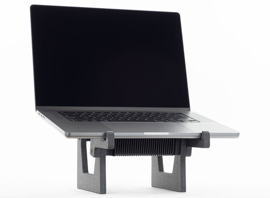
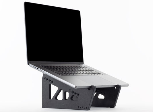
- Stand: SRx / Sx / S Pro: Remove / Install
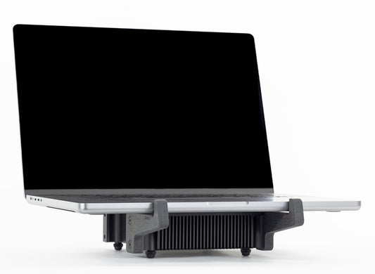
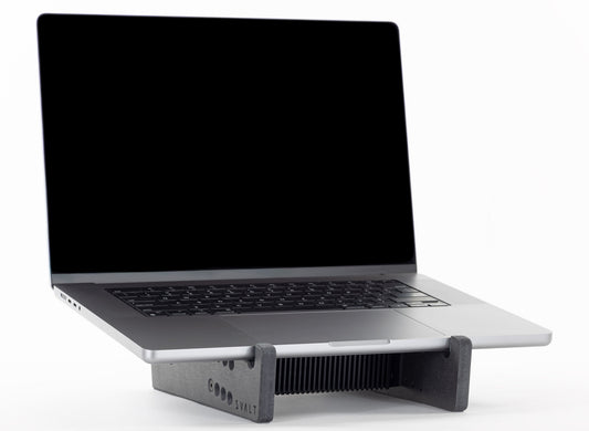
- Stand: SRxM / SxM / S Mini: Remove / Install
- Cleaning
-
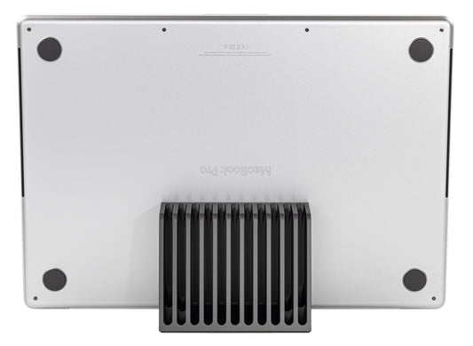
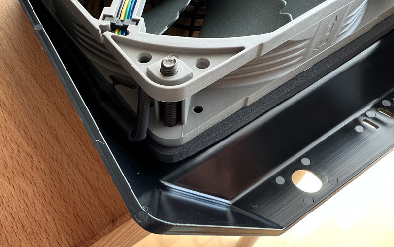
Loosen four fasteners, but do not remove fasteners from the cooling system.
-
Pull out cooling system. -
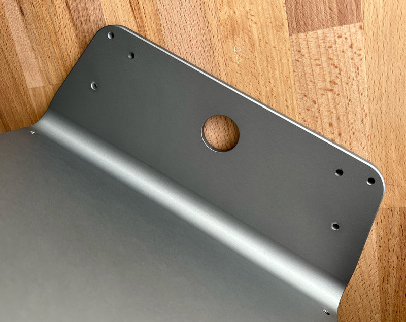
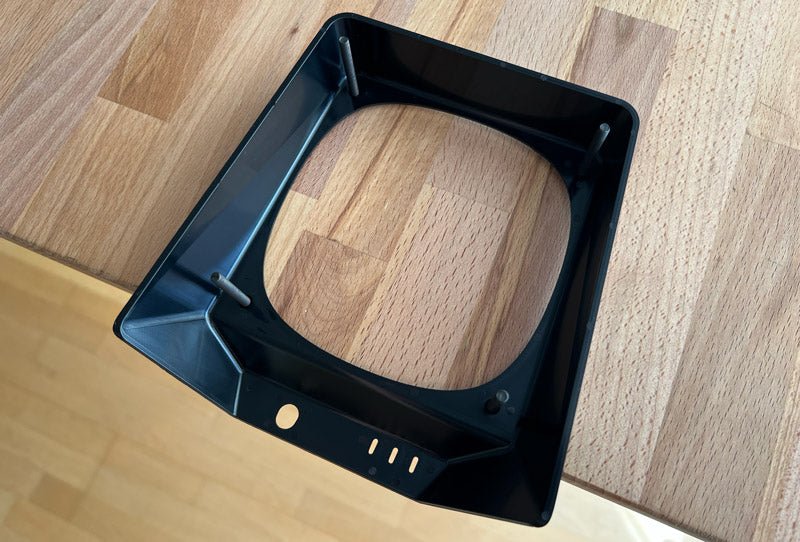
Place the front of dock facedown on a surface that will not scratch the metal finish, such as a work desk or a foam layer from the product packaging. The interior air chamber of the dock should be facing upward.
-
Align the cooling system with the dock interior air chamber opening and insert the cooling system into the dock. If the cooling system and fasteners do not drop fully into the dock, then slightly shift the cooling system and fasteners until they drop into place.
-
Fasten the cooling system to dock. Begin by lightly tightening each of the four fasteners. Once each of the four fasteners has started to thread into the the dock, then tighten each fastener so that the back of the screen just begins to enter into the dock interior pocket. Do not over tighten to avoid damaging screen and other components.
-
Plug the power supply into the fully assembled dock and cooling system (do not plug into a partially or incorrectly assembled dock or cooling system), and press the power switch to confirm that the fan powers on. If the fan does not turn on, then remove the cooling system and check the fan connection (see fan installation guide). -
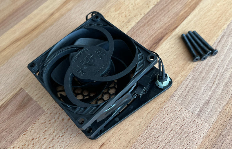
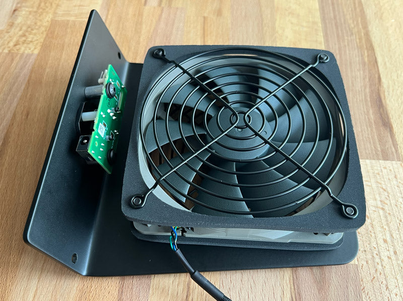
Pull out four fasteners.
-
Pull off tape from bottom edge of fan. Keep tape for reassembly.
-
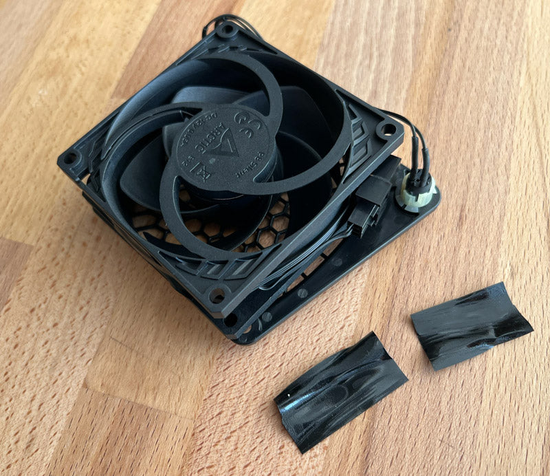
Pull off tape from side edge of fan, next to fan connector. Keep tape for reassembly.
-
Disconnect fan connector. When unplugging the connectors there’s a snap latch that will need to be pulled up to allow the fan connector to disconnect.
-
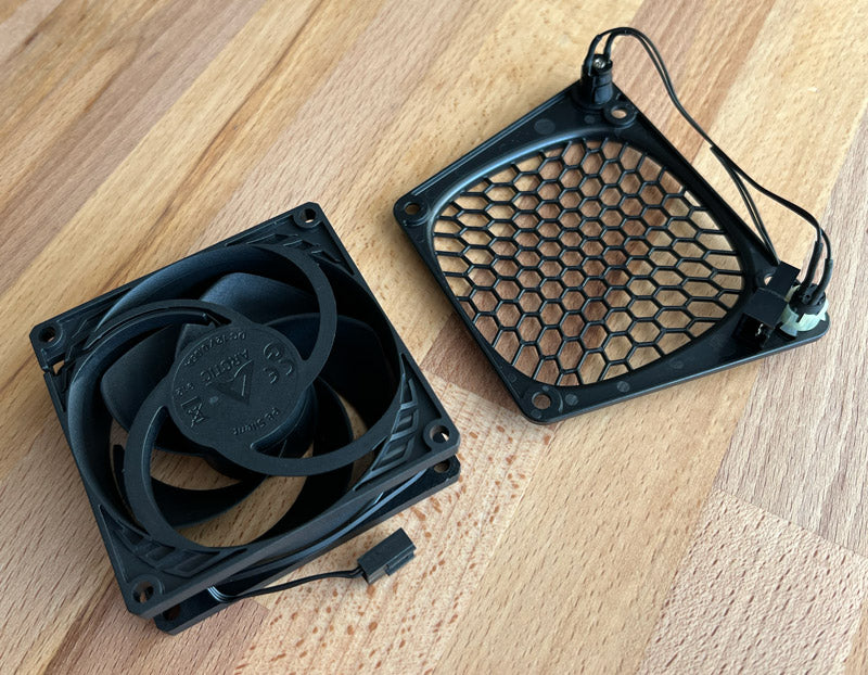
Remove fan from screen and speed control wiring. Note fan’s orientation to help with reassembly. -

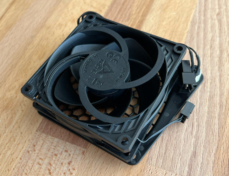
Wrap the fan’s wire around the side of the fan frame. Fans from SVALT will come with the wire taped and pre-wrapped around fan for easier installation. If you are using a fan that does not come from SVALT, then you will need to experiment with how to wrap the fan wiring so that the fan’s connector meets with the screen’s connector. The screen’s connector is setup from SVALT to be positioned on the right side of the fan, but the screen’s wiring length allows for the connector to also be positioned on the left side of the fan if needed.
-
Place a piece of tape at the center of the fan side to hold the fan wiring in place, but still allows the fan connector to have sufficient slack to plug into the screen connector. The purpose of the tape is to hold the wires in place while inserting the cooling system into the dock.
-
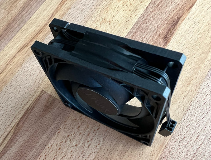
Align fan with screen. Orientate the fan so that the fan’s intake side is next to the screen and the fan’s exhaust side (the fan’s exhaust side includes fan blade motor mounting and support frame) faces the inside of the dock’s interior air chamber when installed. Rotate the fan so that the fan’s wire connector aligns with the screen’s wire connector.
-

Plug the fan connector into the screen connector. The fan connector and cooling system will work with either 3-pin or 4-pin fans using a standard miniature fan connector.
-

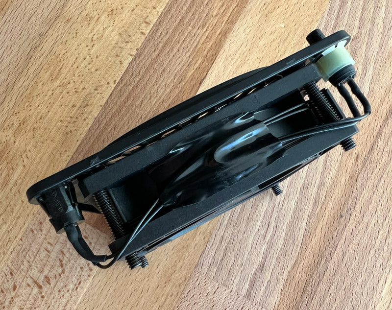
Feed the fasteners through the screen and fan. The two upper fasteners slide over the fan wiring. The two lower fasteners slide over the fan wiring and the screen wiring leading into fan connector, but slide under the screen wiring leading from the screen switch and plug components.
-
Place a piece of electrical tape at the center of the bottom edge of the fan to hold wires in place. Spread the wires out and position them so that they do not overlap under the tape. The purpose of the tape is to hold the wires in place while inserting the cooling system into the dock.
-
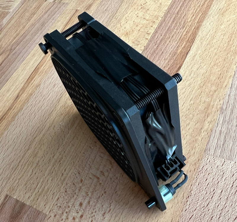
Place a piece of electrical tape above the fan connector along the side of the fan. If there is slack in the fan wire, then the wire can be tucked under the top fastener and within the fan’s recessed corner. The purpose of the tape is to hold the wires in place while inserting the cooling system into the dock. -
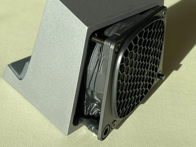
- Loosen but do not fully remove the four fan fasteners.
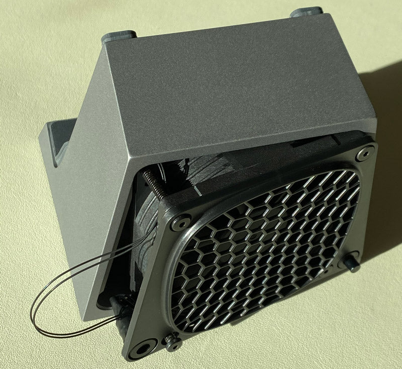
- Once fasteners have been unscrewed from the aluminum dock, then carefully shift the fan screen from side-to-side while slowly pulling out the cooling system. Only pull out the cooling system to the point that the side of the fan is exposed while the rest of the fan and cooling system remains within the aluminum dock.
-
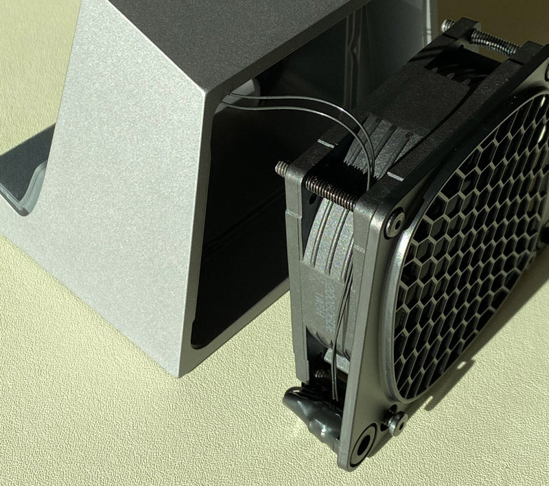
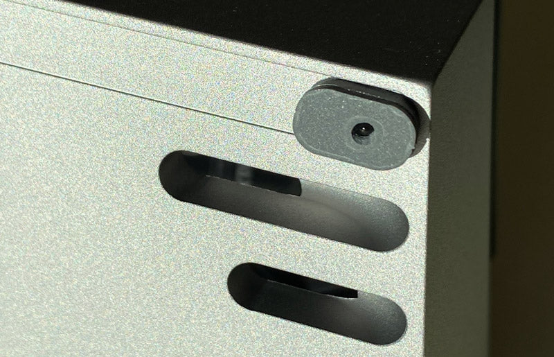
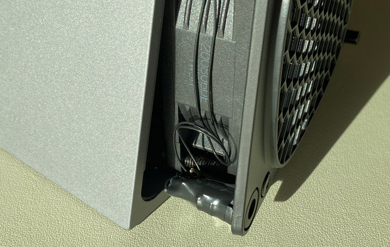
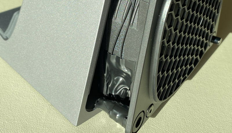
- On the left side of the fan (the side with the power jack) there is a piece of black electrical tape holding the thermistor wire against the fan. Remove the tape to free a coil of excess thermistor wire.
- Once the thermistor wire is free, continue to pull out the cooling system so that it is fully outside of the aluminum dock but the thermistor wire still has some slack in it’s connection to the aluminum dock.
- Important Note: For original D2 and D2 Legacy models, this is as far as a cooling system can be removed. Further disassembly will require reassembly beyond the scope of this guide or require returning the dock to SVALT for reassembly.
-
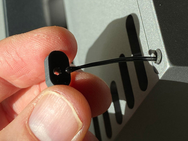
- The thermistor head is held within two layers of front top right pads and a foam alignment plug behind.
- Peal off the upper/outer 1/16” thick pad from the lower/inner 1/8” thick pad.
- Peal off the lower/inner 1/8” thick pad from the aluminum dock.
- Carefully push the front of the thermistor head through the 1/8” thick pad hole. Do not pull the thermistor wires, and only push on or pull from the thermistor head to avoid damaging the thermistor.
- A foam thermistor wire alignment plug may fall out, if it does not fall out, then pull it out and put aside.
- Remove any loose / excess adhesive from where the old front top pads were located on the aluminum dock.
- Important Note: Removing the thermistor and pads will require new replacement pads that can be purchased through the accessories page.
-
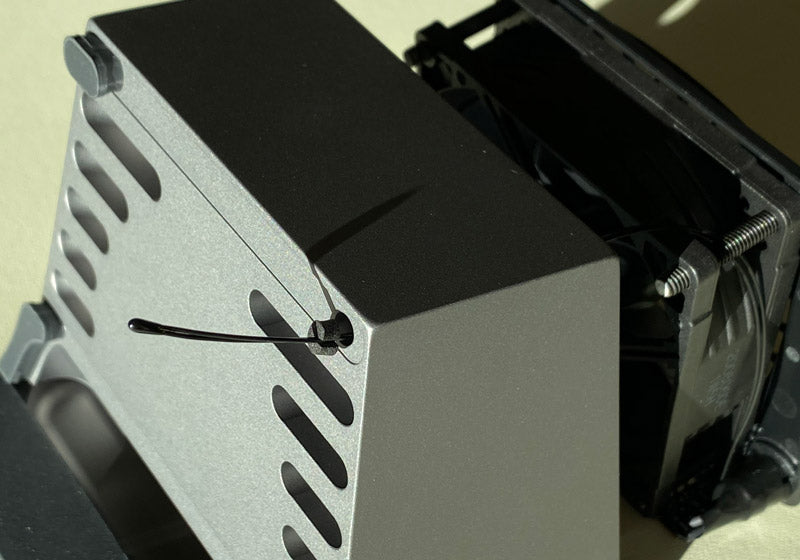
- Pull the thermistor wire and head through the hole in the aluminum dock and towards the cooling system. -
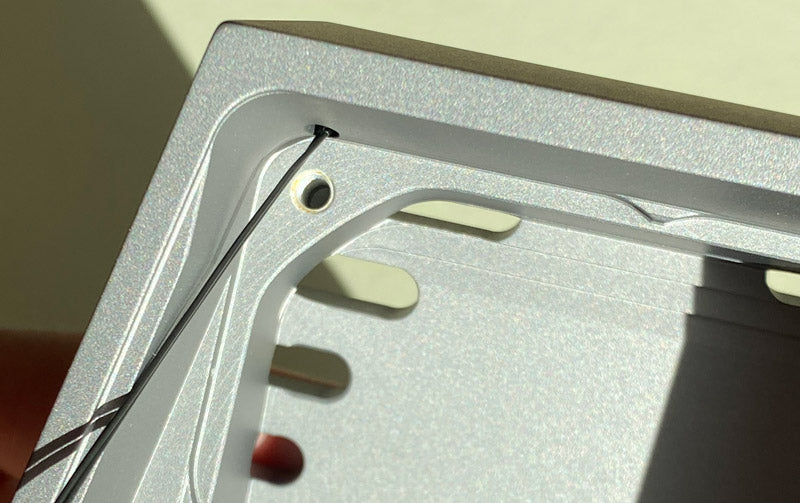
- Insert the thermistor head through the thermistor pass-through hole on inside of the aluminum dock, but do not put the cooling system into the aluminum dock, and keep the cooling system outside of the dock.
-
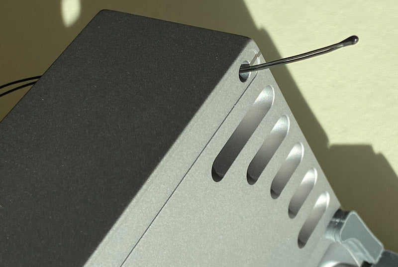
- Pull the head of the thermistor wire through the front hole so that it extends one inch past the dock.
-
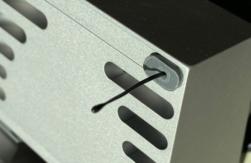
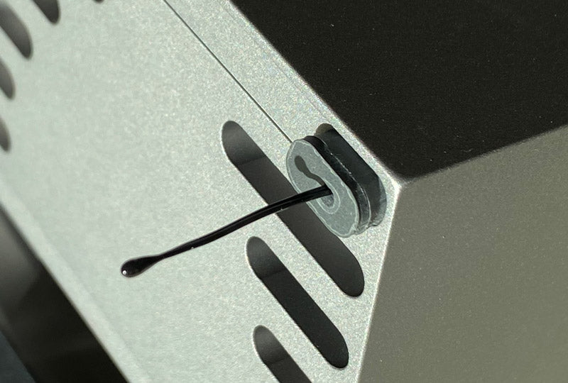
- Fit the foam thermistor alignment plug over the wire.
-

- Push foam plug into the hole cutout.
-
- Take a 1/8” thick top pad and remove the adhesive cover.
- Take the thermistor head and position it within the hole of that pad, entering from the back adhesive side.
- Use needle noose pliers or tweezers to grip the back of the thermistor head (do not grip the wires as that will damage the thermistor), and push the head all of the way through the pad hole.
-
- With thermistor head fed through and extended out beyond the pad, then slide the 1/8” pad down the wire to adhere to the dock.
-
- Take a 1/16” thick top pad and remove the adhesive cover.
- Take the thermistor head and position it within the hole of that pad, entering from the back adhesive side.
- Use needle noose pliers or tweezers to grip the back of the thermistor head (do not grip the wires as that will damage the thermistor), and push the head all of the way through the pad hole.
- With thermistor head extended out past the pad, install the 1/16” pad on top of the 1/8” pad.
-
- Push the thermistor head while gently pulling the thermistor wire from within the dock’s back air chamber.
- Push the thermistor head into the pad to the point that it is just below the outside surface of the top 1/16” thick pad.
- Once the head is set within the pad hole, firmly press the pads into the dock to create a strong adhesive bond.
-
- Pull the thermistor wire from the back and through the gap between the top left fan fastener and the fan frame so that loose wire is on the left side of the fan (note that the thermistor wire must be located under the fastener and cannot be located above the fastener).
-
- Align the cooling system with the dock’s back cutout, and insert only the right side while leaving the left side of the fan angled out.
-
- Coil the excess thermistor wire towards the bottom of the fan.
-
- Place a piece of electrical tape over the coiled wire to hold it in place.
-
- Carefully insert the cooling system into the dock.
- Note that the D2n Pro’s fan fasteners sit higher so you may need to push down on the fan screen to achieve alignment.
-

- Tighten fasteners. Typically any fastener will align and allow the tightening process, but if the first fastener you try to tighten does not find it’s threading, then try another.
- Note that the D2n Pro’s cooling system might need wiggling/shifting to get a first fastener to grab, after which the remaining fasteners will align and thread more easily.
- Do not over tighten fasteners. Only tighten until the back of the screen just begins to enter into the aluminum dock. Over tightening can damage the screen and other components.
-

- Plug the power supply into the fully assembled dock with cooling system (do not plug into a partially or incorrectly assembled dock and/or cooling system), and press the power switch to confirm that the fan powers on per the D2 operation guide. -
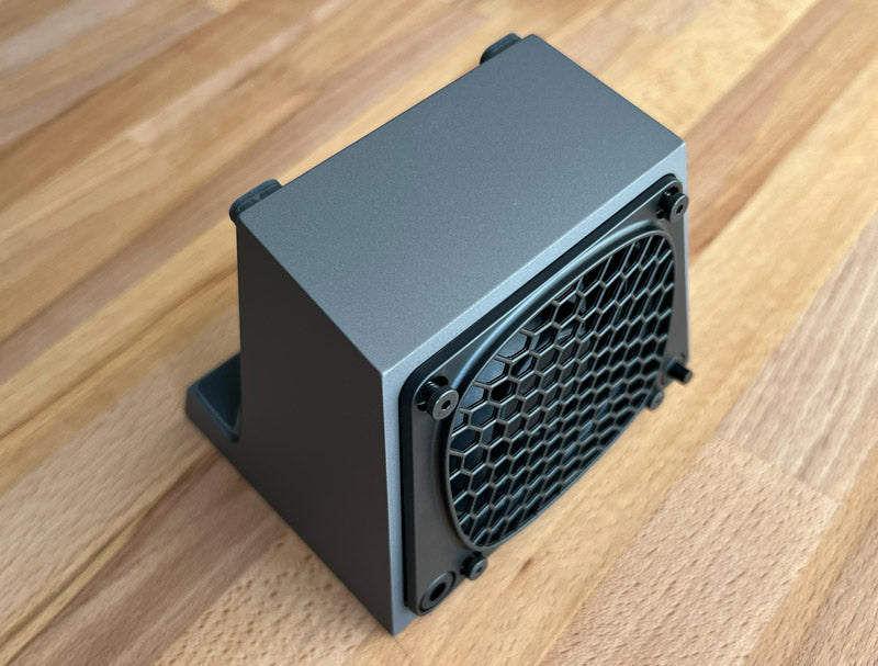
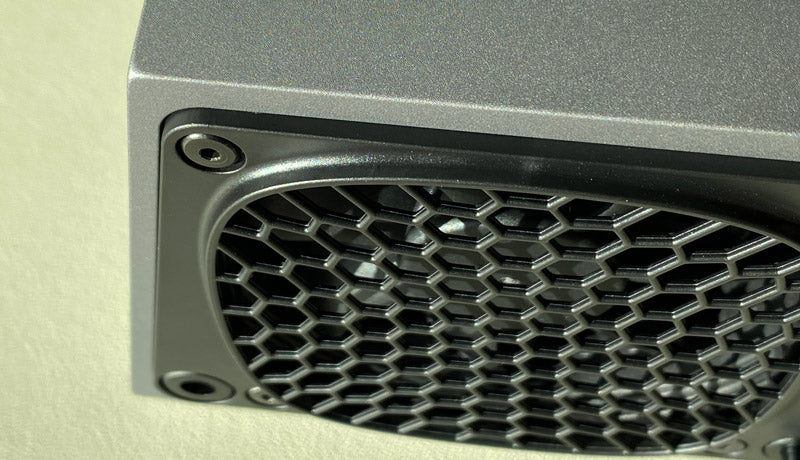
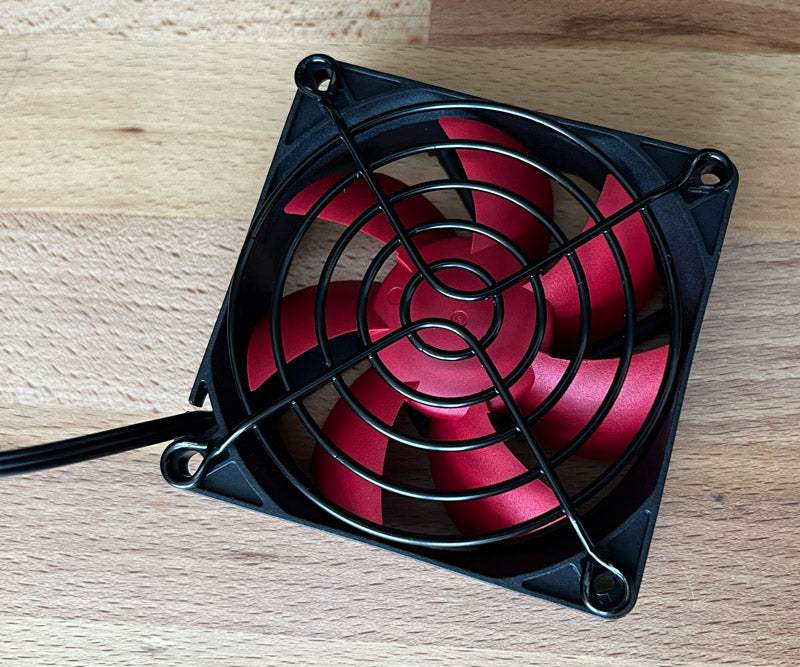
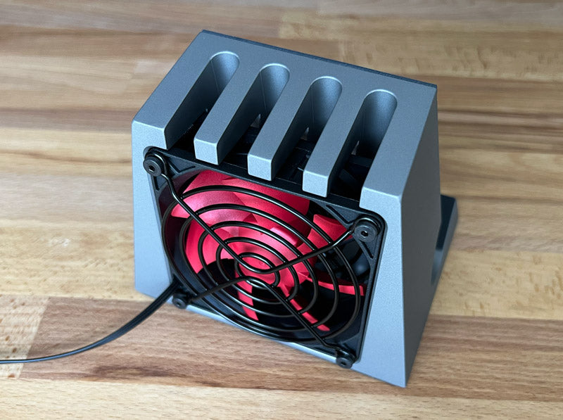
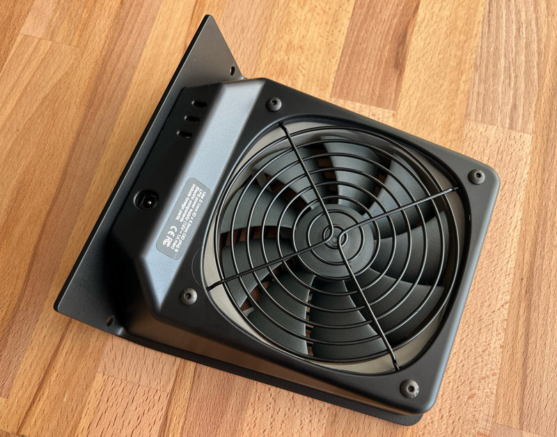
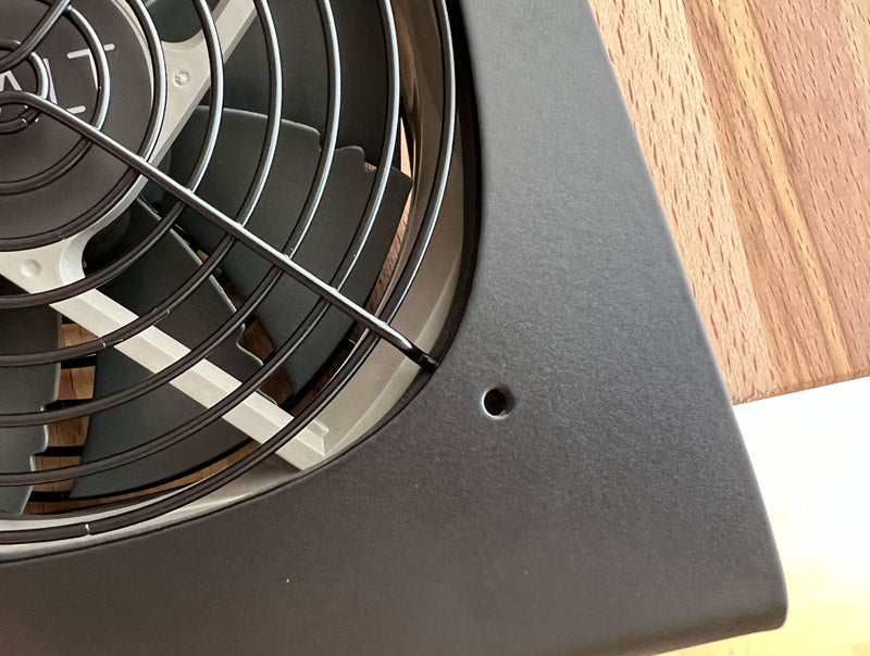
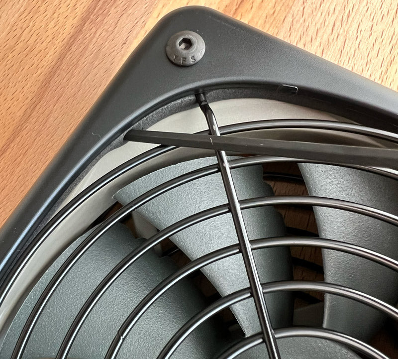
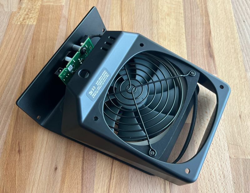
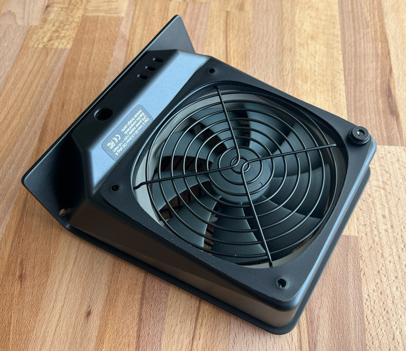
Position the DHCx on it's front face (place material on surface as needed to protect against damage). Use the provided hex key to loosen the four #8-32 fasteners, but do not remove fasteners from the fan.
-
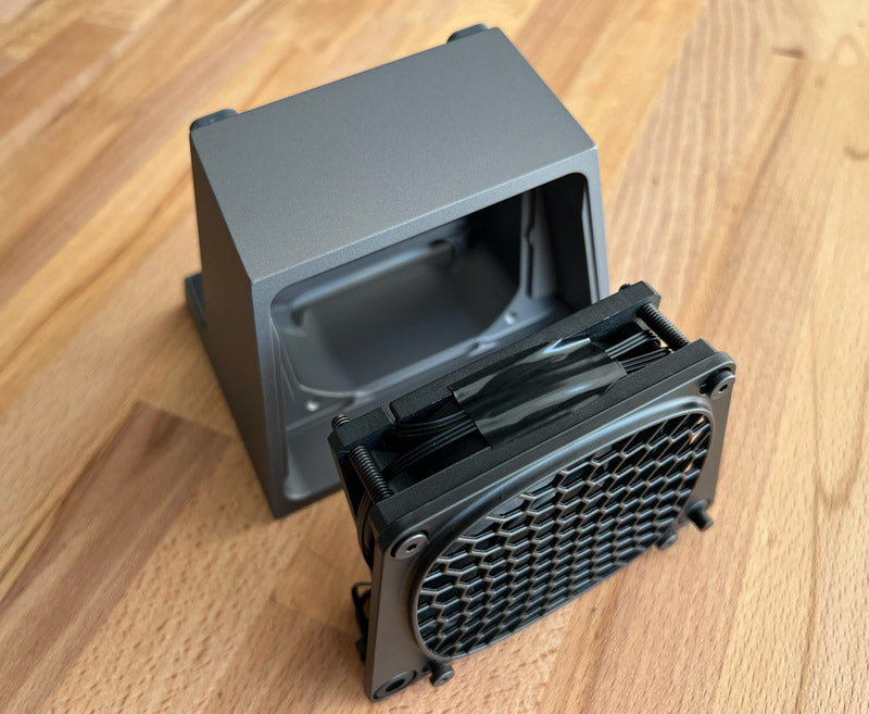
Position the DHCx upright, and pull out the fan with finger guard screen and fasteners.
-

Remove the inner screen if it does not come out with the fan.
-

Remove the outer finger guard and fasteners from fan.
-
Use a compatible fan per DHCx product page specifications. Insert the fan wire into the fan frame's wire notch on the intake side of the fan (the intake side of the fan is opposite of the exhaust side of the fan that typically has the fan blade motor mounting and support frame). If the fan frame does not include a wire notch, then in most cases a notch can be cut into the frame without impacting fan functionality. Note that the fan fits tightly within the heatsink’s fan cutout to create an air seal and prevent air from leaking out.
-
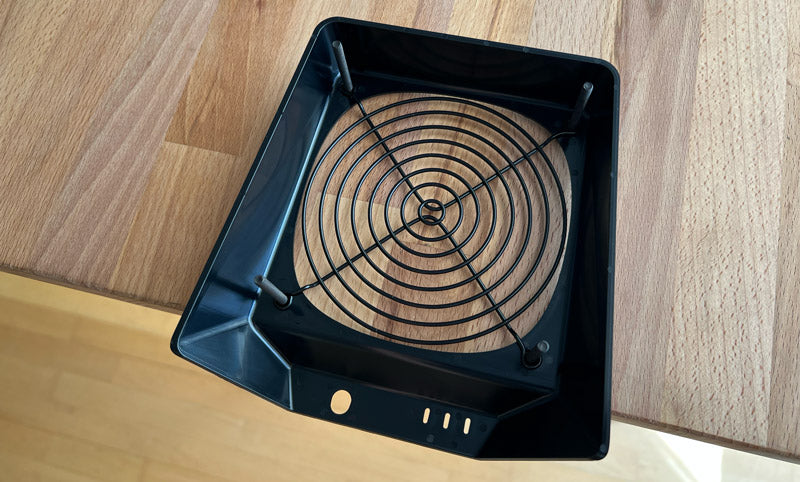
Place a fan finger guard screen on top of the intake side of the fan. Orientate the screen so that its outward extending side will project beyond the fan when installed.
-
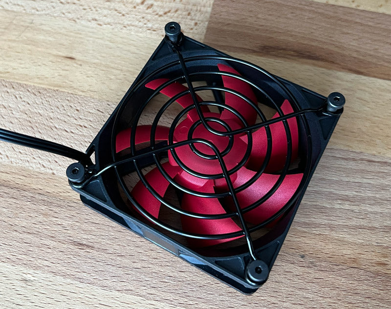
Insert the four #8-32 fasteners through the screen and fan mounting holes.
-
Position the fan with screen and fasteners upright so that the fan wire is located on the lower side.
-
Place the second screen into the DHCx. Orientate the screen so that its outward extending side will project beyond the fan and contacts the heatsink's cooling fin surface.
-
Align fan assembly with DHCx.
-
Insert fan assembly into DHCx.
-
Position the DHCx on it's front face (place material on surface as needed to protect against damage). Tighten fasteners, but do not over tighten to avoid crushing fan. To initiate fastener threading, you may need to press down lightly on the hex drive and fastener.
-
Position DHCx upright.
-
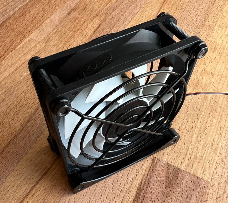
Use fingers to loosen the top two fasteners and nuts, but do not remove the fasteners and nuts.
-
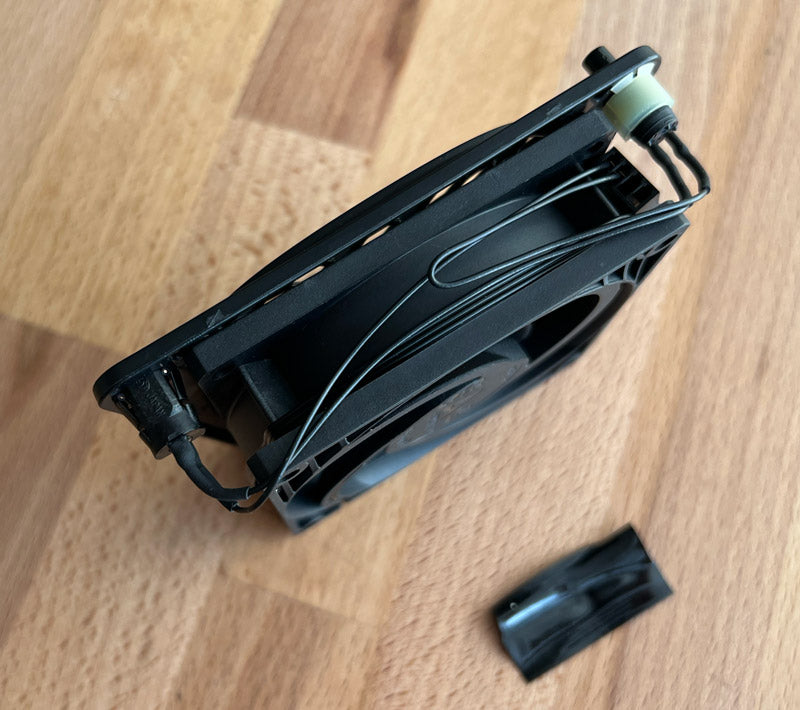
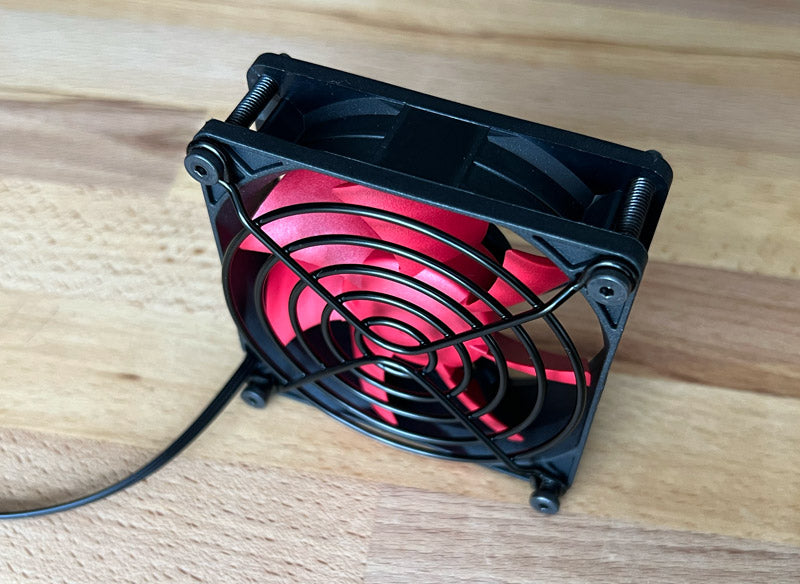
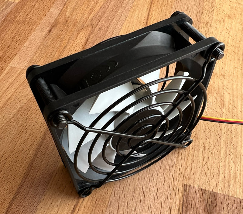
Flip the Fx over onto the top edge of the fan.
-

Loosen the two fasteners in the fan feet until the threaded fan foot can be removed.
-
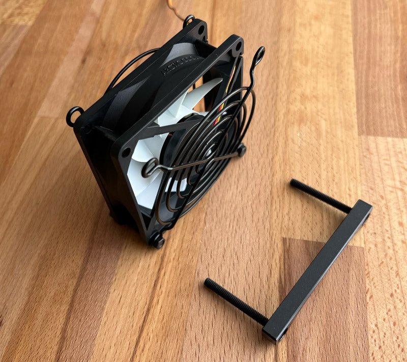
Pull the counterbore fan foot and fasteners out of the fan.
-
Pull the fasteners from the fan foot.
-

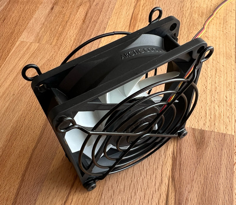
Flip the fan over onto the bottom edge of the fan.
-
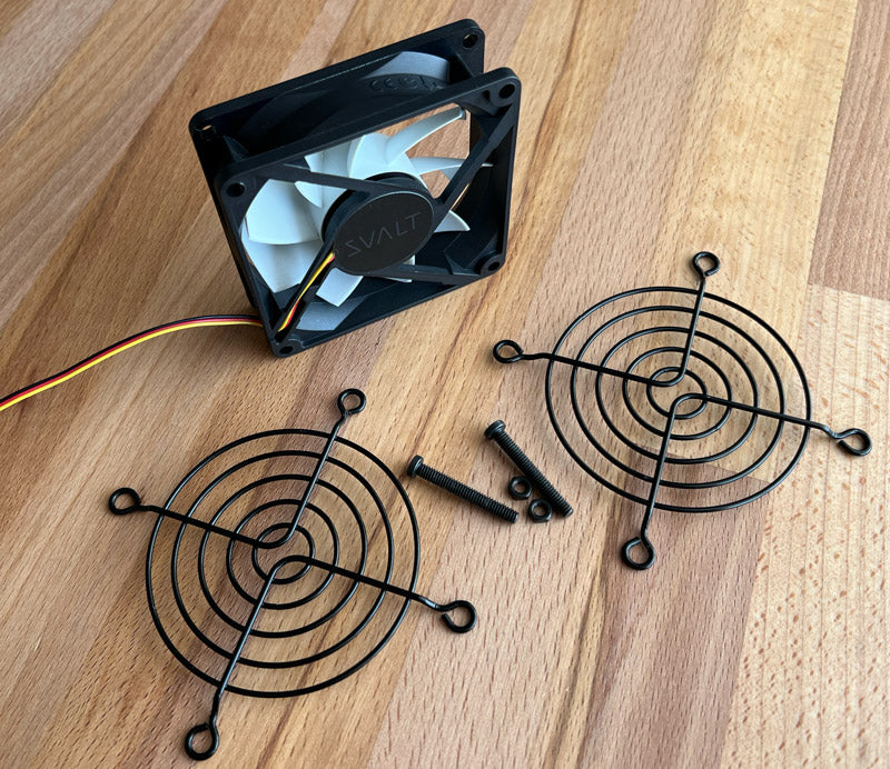
Remove the two nuts, two fasteners and two screens. -
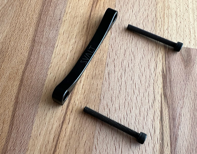
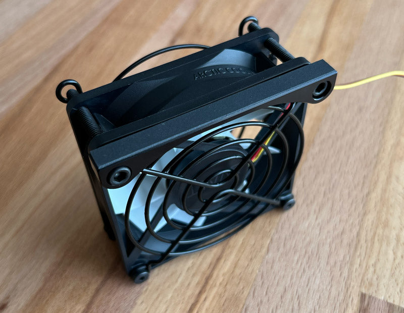
Insert the two shorter and smaller fasteners through the front side of one of the screens. Orientate the screen so that its outward extending side will project beyond the fan when installed.
-
Insert the fasteners and screen into the top holes of the fan. Orientate the fan so that fastener heads are on the fan’s exhaust side (the fan’s exhaust side includes fan blade motor mounting and support frame), and the fan’s wiring exits the fan at the bottom.
-
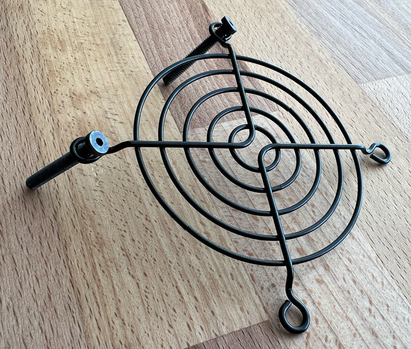
Insert the second screen onto the fastener ends that project through the other side of the fan. Orientate the screen so that its outward extending side will project beyond the fan when installed.
-

Thread nuts onto fastener ends by hand. Lightly tighten nuts only enough to keep the assembly held together, do not over tighten so that the assembly cannot move freely.
-
Flip the assembly over onto the fan’s top edge so that fasteners and nuts are positioned below.
-
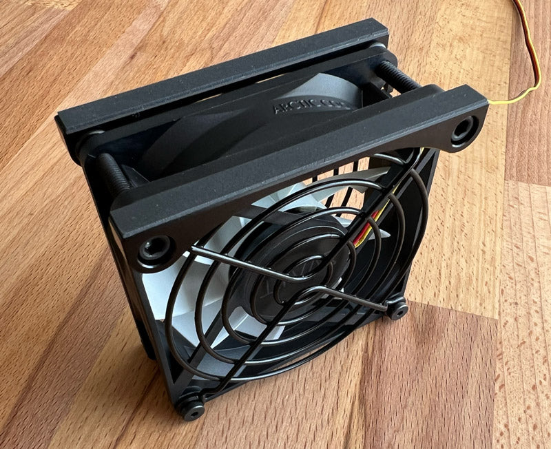
Insert the two longer and larger fasteners through the fan foot with counterbore through holes.
-
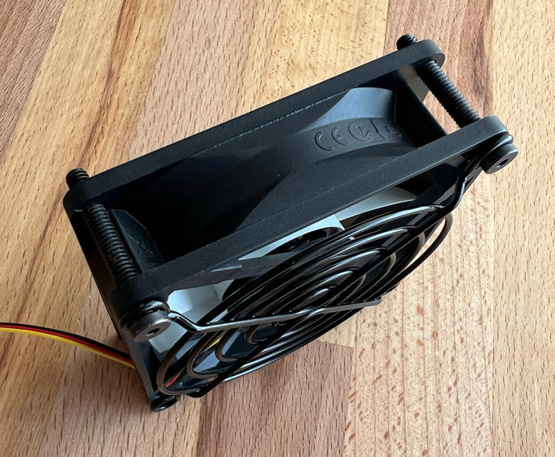
Insert the fan foot with two fasteners through the fan’s exhaust side (the fan’s exhaust side includes fan blade motor mounting and support frame). Orientate the fan foot so that its non-slip pad is facing upward and the foot’s curving top surface is next to the screen.
-
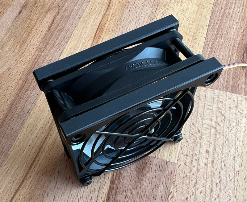
Align the threaded fan foot with the fasteners ends and thread the fasteners into the threaded fan foot. Orientate the fan foot so that its non-slip pad is upward and the foot’s curving top surface is next to the screen. Lightly tighten fasteners only enough to keep the assembly held together, do not over tighten so that the assembly cannot move freely.
-
Flip the assembly Fx over onto the feet non-slip pads and place on a flat surface. Lightly press down on the top of the fan assembly so that the feet level with the flat surface. Tighten the two fan foot fasteners. This will lock in a level assembly. Only tighten fasteners to the point that the assembly does not move around. Do not over tighten as the fan frame can easily be crushed. Hand tighten the two upper fasteners and nuts. -
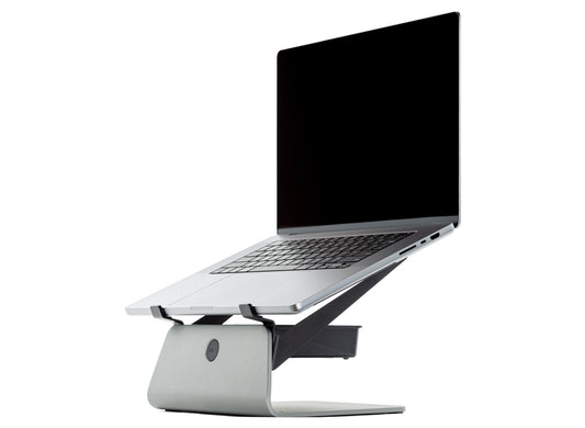
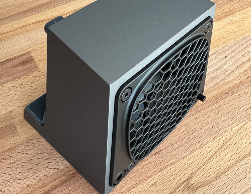
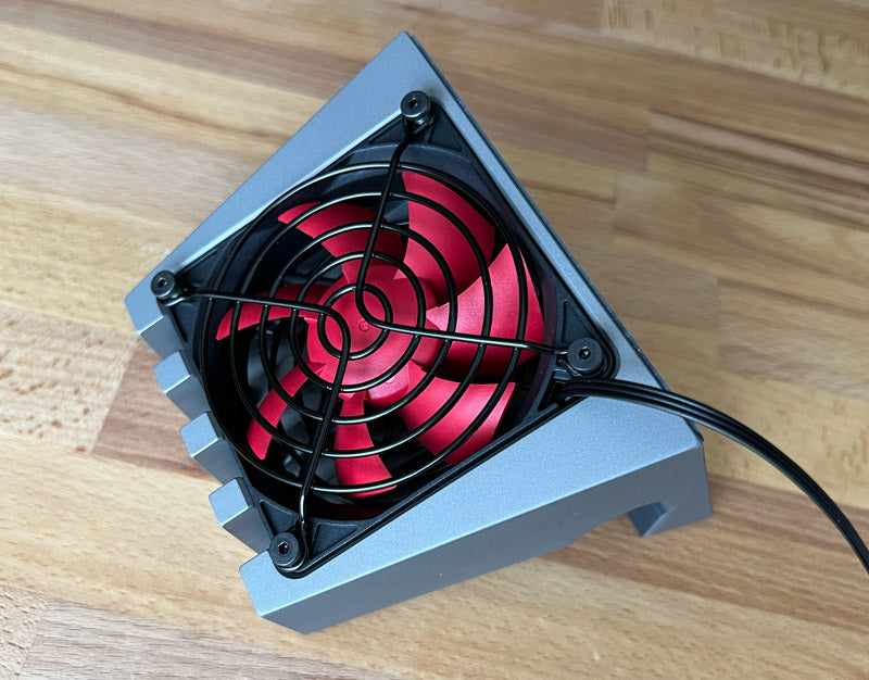
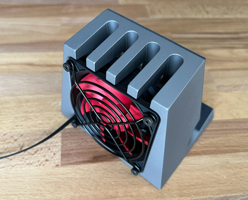
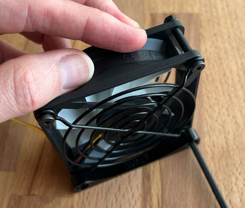
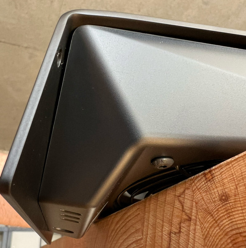
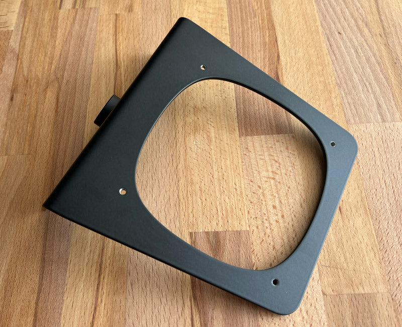
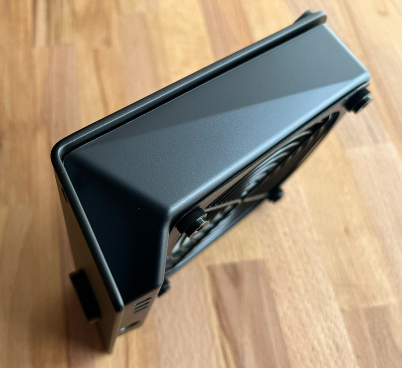
Place the front of Cooling Stand facedown on a surface that will not scratch the metal finish, such as a wood desk or a foam layer from the product packaging. If the Laptop Support Arms are installed, then they can be left in place and the Cooling Stand will rest on the arm's front support tabs.
-
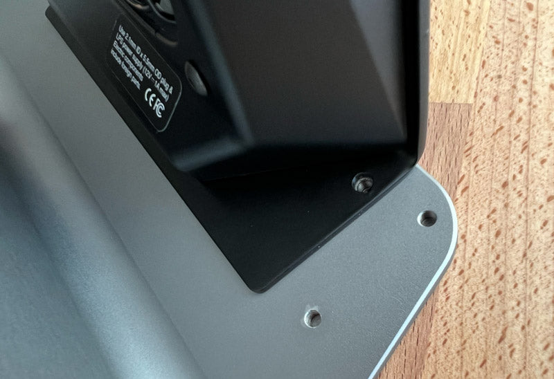
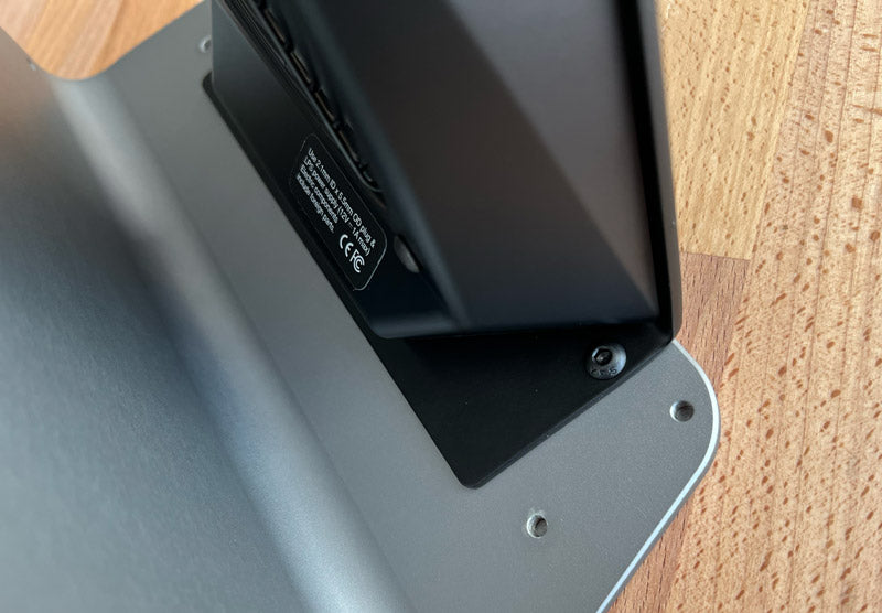
Remove the two fasteners. Hold the top of the cooling unit before removing the second / last fastener so that it does not tip over.
-
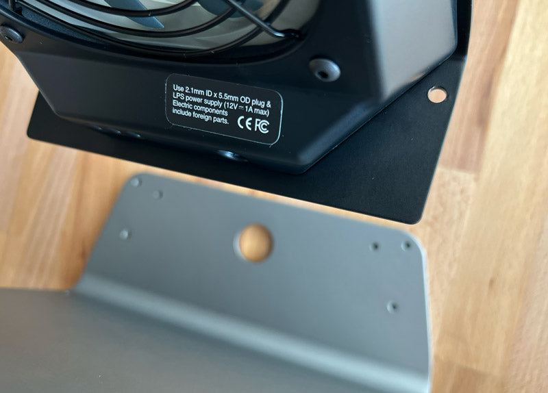
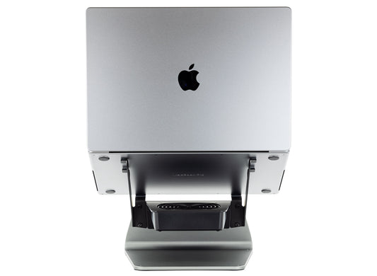
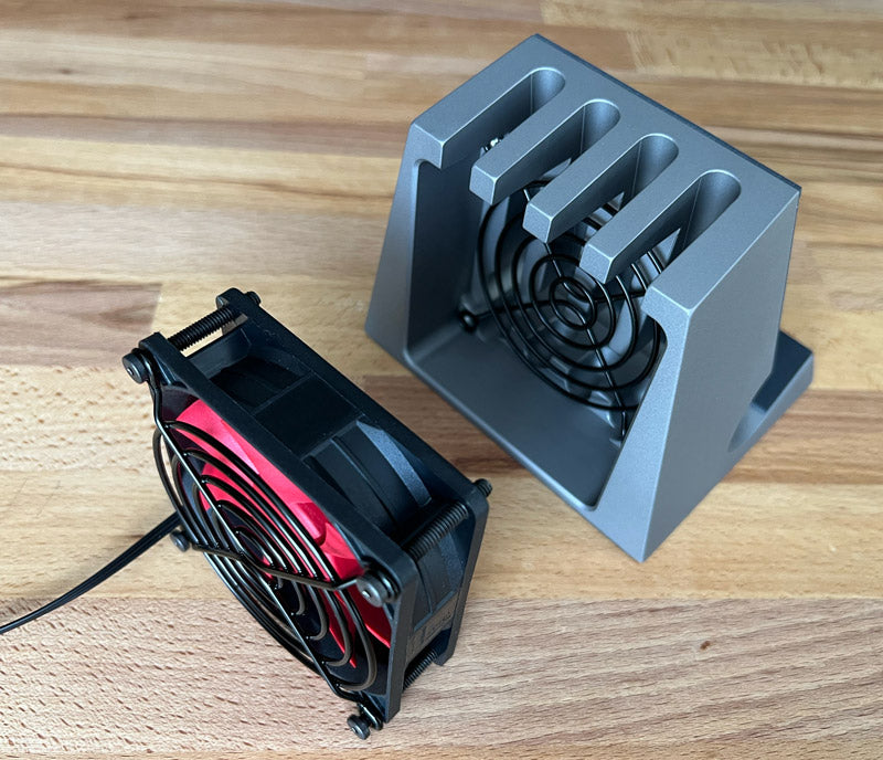
Pull the cooling unit straight up so that the cooling unit's black anodized aluminum pushbutton switch does not get damaged when being extracted from the SRx Support Plate’s or Sx Support Base's switch hole. -
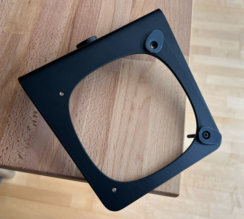
Place the front of Cooling Stand's SRx Support Plate or Sx Support Base facedown on a surface that will not scratch the metal finish, such as a wood desk or a foam layer from the product packaging. If the Laptop Support Arms are installed, then they can be left in place and the Cooling Stand will rest on the arm's front support tabs.
-
Line up the cooling unit's black anodized aluminum pushbutton switch with the SRx Support Plate’s or Sx Support Base's center switch hole. Carefully insert the pushbutton switch into the center switch hole.
-
Align the two fastener holes, insert fasteners and thread fasteners to a light tightness.
-
Click on front pushbutton switch and note if any edge of the pushbutton switch rubs or scratches against the sides of the through hole. If this occurs, then place the front of the Stand facedown and slightly loosen fasteners then slide the cooling unit slightly in the direction that will reduce the switch rubbing / scratching. Retighten and recheck for rubbing / scratching. Once adjusted, then tighten fasteners but do not over tighten or strip threading. -
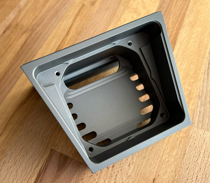
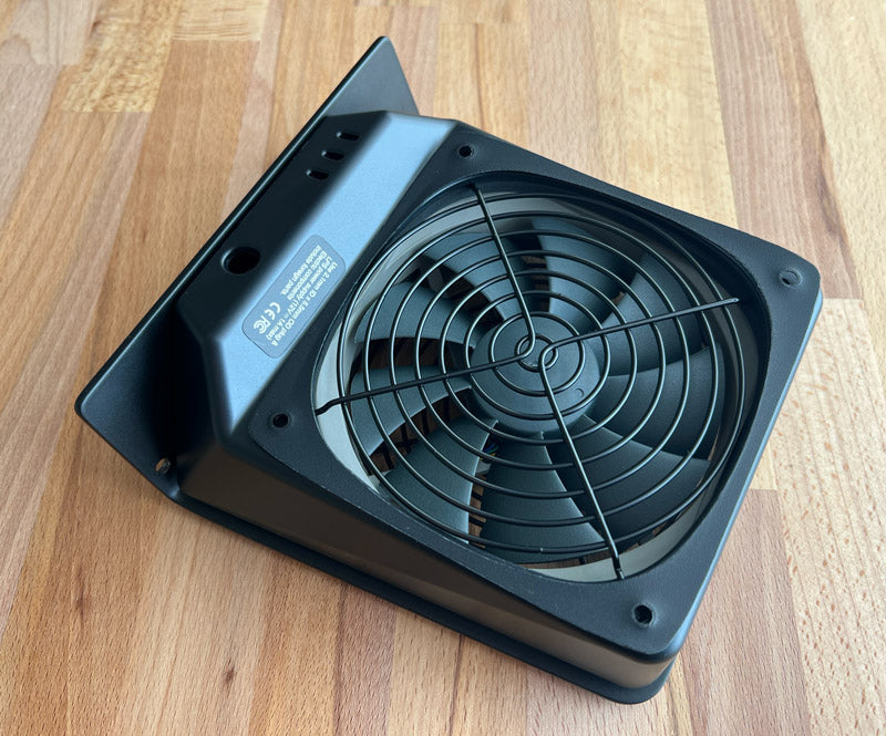
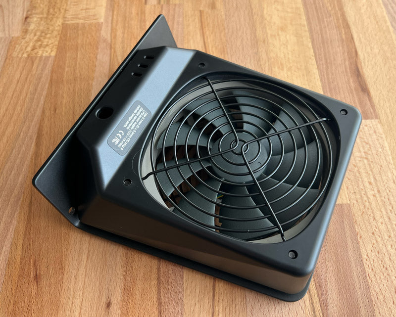
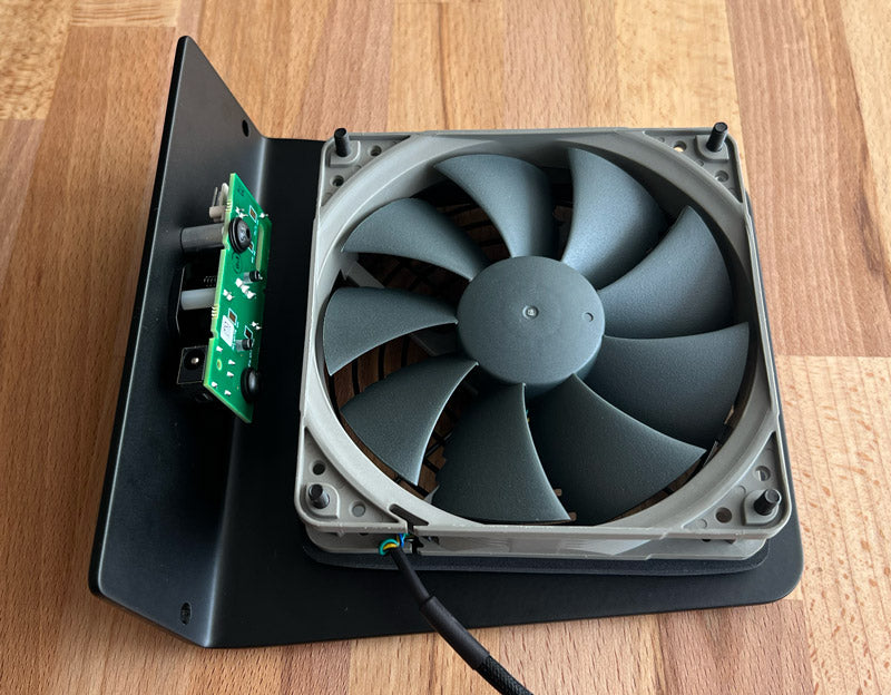
Turn cooling unit upside down so that the four fastener heads are exposed.
Loosen four fasteners but do not remove fasteners from assembly.
-

Flip the cooling unit over and place the flat bottom of the plastic enclosure on the edge of a wood desk or a foam layer from the product packaging. This positions the flat bottom of the plastic enclosure on a flat surface and holds the four fasteners in place during disassembly.
-
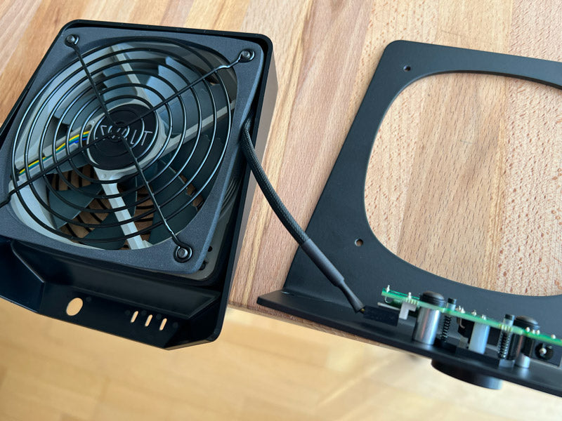
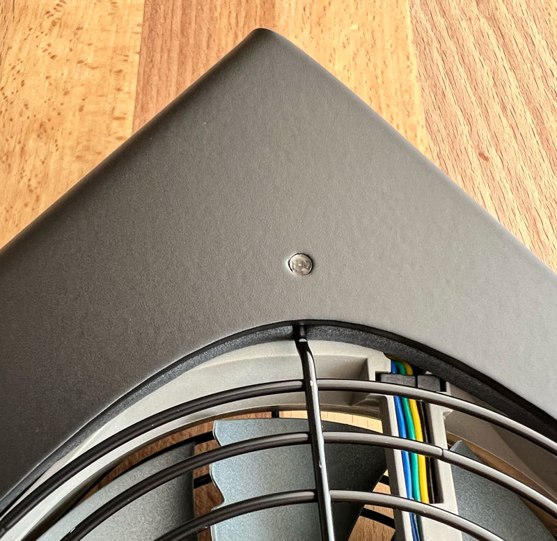
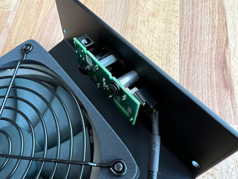
Separate the top metal support enclosure from the plastic enclosure and fan assembly. Do not pull hard on the metal support and connect fan wire. Pull up on the metal support enclosure only enough to separate it and expose where the fan wire connects to the speed control unit.
-
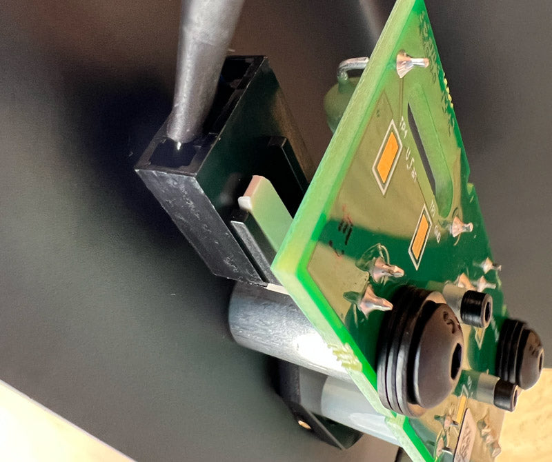
Unplug the fan wire connector from the speed control unit connector. Take note of the fan connector’s position before unplugging to help with reassembly. When unplugging the connectors, there’s a snap latch that will need to be pulled up to allow the fan connector to unplug. Do not touch the speed control unit other than the plastic snap latch.
-
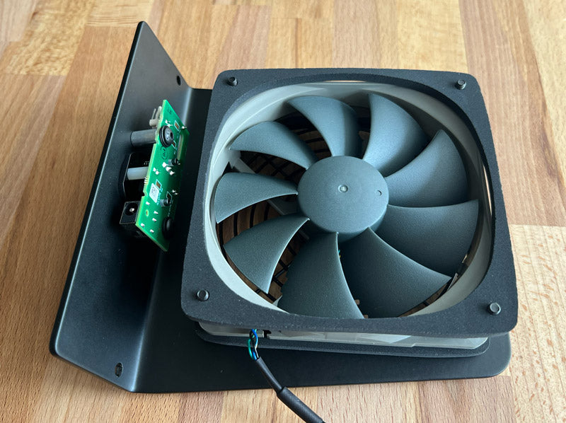
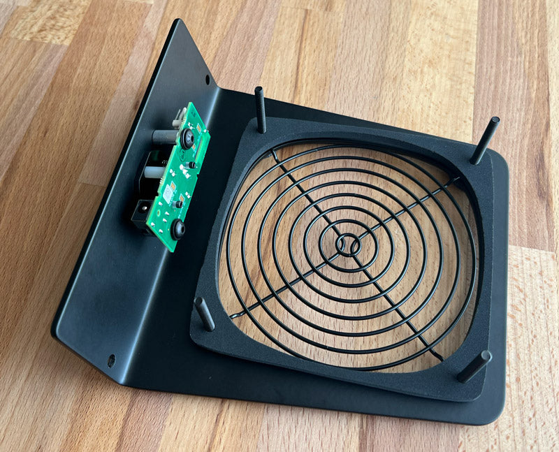
Remove the top black metal finger guard and foam gasket. Take note of the guard’s orientation to help with reassembly.
-

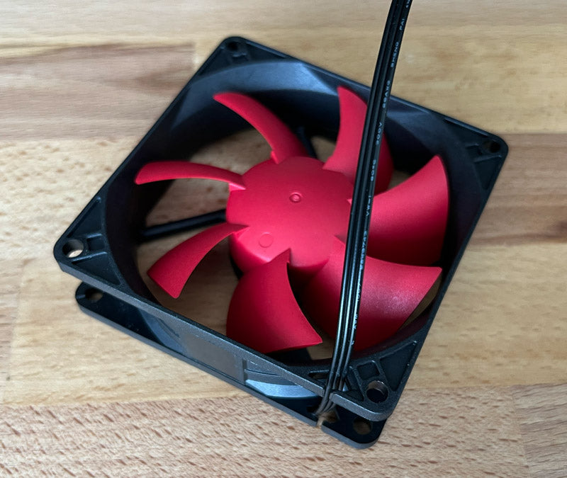
Remove the fan wire and fan. Take note of the fan’s orientation to help with reassembly.
-
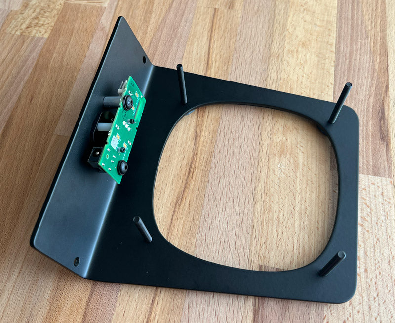
Remove the bottom gasket and guard if needed for cleaning or other purpose. Take note of the guard’s orientation to help with reassembly. -
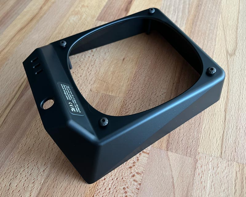
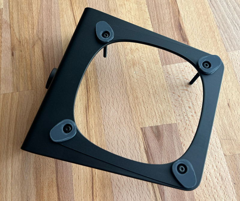
Feed four #8-32 x 1 1/2” fasteners through the bottom of the four holes in the plastic enclosure.
-
Place the plastic enclosure with inserted fasteners on the end of a wood desk or on the edge of a foam layer from the product packaging. This positions the flat bottom of the plastic enclosure on a flat surface and holds the four fasteners in place during assembly.
-
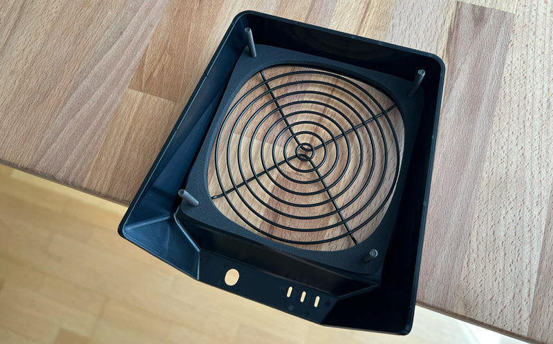
Feed one of the black metal finger guard through the four fasteners. Note that the guard extends outward, and orientate the guard so that it extends downward in order to move the guard further from the fan for reduced noise.
-
Feed one of the foam gaskets through the four fasteners. Adjust the gasket so that it lays flat, is free of distortions and aligns with the plastic enclosure’s air opening below.
-
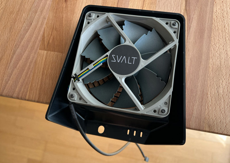
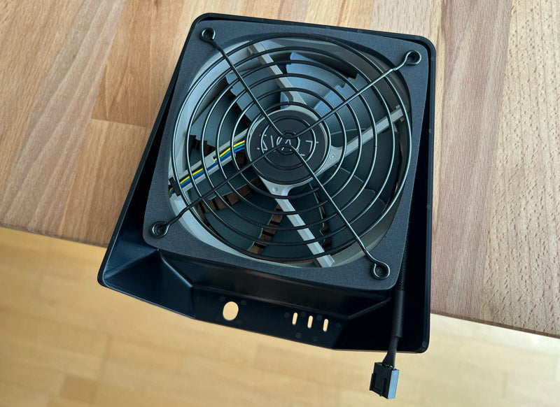
Feed the fan through the four fasteners. Orientate the fan so that the fan’s intake side is facing down and exhaust side is facing up (the fan’s exhaust side includes fan blade motor mounting and support frame). Rotate the fan so that the SVALT logo is orientated upright and the fan wiring exists at the lower left corner. Leave the fan wiring to hang freely.
-
Wrap the fan wiring clockwise around the fan and tuck the wiring into the lower right corner. Orientate the fan connector so that the raised ridges are facing inward (to the left). Leave 1.5 inches of the wiring and fan connector extending out.
-
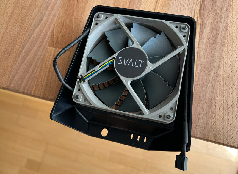
Tuck the fan wiring around the sides of the fan.
-
Push the fan wiring down on the left side where it exists the fan frame.
-
Feed the second foam gaskets through the four fasteners. Adjust the gasket so that it lays flat, is free of distortions and is centered on the fan below.
Feed the second black metal finger guard through the four fasteners. Little to no fastener may protrude beyond the foam gasket, in which case, place the screen on top of the gasket and aligning with gasket fastener holes. Note that the guard extends outward, and orientate the guard so that it extends upward in order to move the guard further from the fan for reduced noise.
-
Hold the top metal support over the fan assemble and attach the fan connector to the speed control system’s fan connector. Orientate the fan connector so that the rails align and then insert the two connector prongs into the lowest two holes on the fan connector. Note that if the fan does not power up after assembly, then it is likely that the connector was inserted into the incorrect holes on the fan connector.
-
Place the top metal support over the fan. Align the four threaded holes with the fastener ends.
-
Partially thread the lower right fastener into the metal support enclosure. Position the assembly so that the fastener head can be accessed while the rest of the assembly and other three fasteners stay resting on the surface. When the fastener end is aligned with the threaded hole, press upward on fastener while turning fastener. Only tighten fastener so that the fastener has begun to enter threading and will not fall out. Do not over tighten and loosen fastener if needed.
-

Flip the cooling unit over and partially thread the other three fasteners in the metal support enclosure. Rotate the assembly so that it is vertical to access the fastener heads. Only tighten fasteners so that the fastener has begun to enter threading and will not fall out. Do not over tighten and loosen fasteners if needed.
-

Adjust top gasket. Return assembly with top up and inspect the gasket to see if any portion is extending into the fan opening. Use the end of the hex key or other tool to push the gasket into place as needed.
-
Adjust bottom gasket. Flip the assembly over and repeat the gasket inspection and adjustment as needed.
-
Tighten fasteners. Begin to tighten the four fasteners by partially tightening one and then another. Tighten fasteners so that the rim edge of the plastic enclosure meets the metal support enclosure. The the metal support and plastic enclosure do not require a tight fit, so do not over tighten. See the next step to help achieve proper fastener threading and tightness.
-
Do not over tighten fasteners. The ends of the fasteners should not extend beyond the top surface of the metal support enclosure, and should stay slightly recessed within the holes. Over tightening the fasteners can damage components.
-
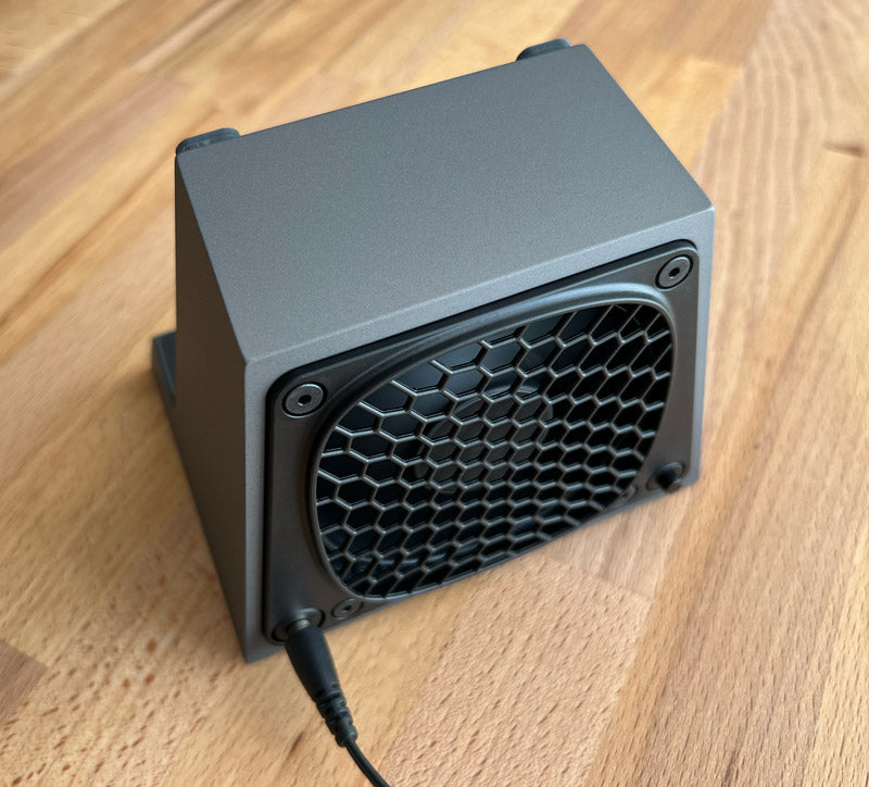
Plug the power supply into the fully assembled cooling unit (do not plug into a partially or incorrectly assembled cooling unit), and cycle through the fan speeds. If the fan does not turn on, then the fan connector may need to be repositioned as noted above in step number 10. -
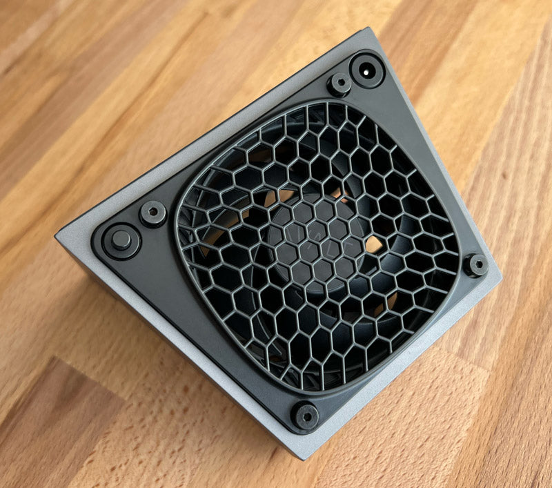
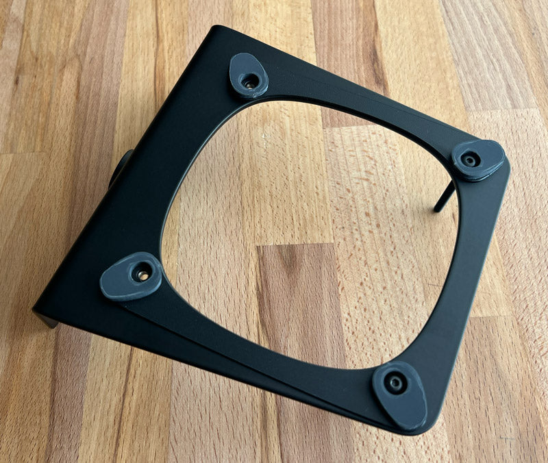
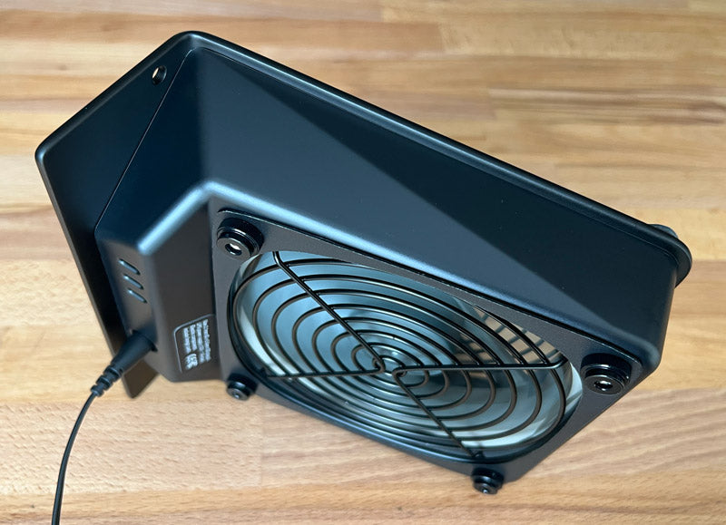
Flip the cooling unit over onto the Mac Mini support pads.
-
Remove the four finger tightening nuts.
-
If installed, remove the dust filter frame and dust filter.
-

Remove the plastic enclosure.
-
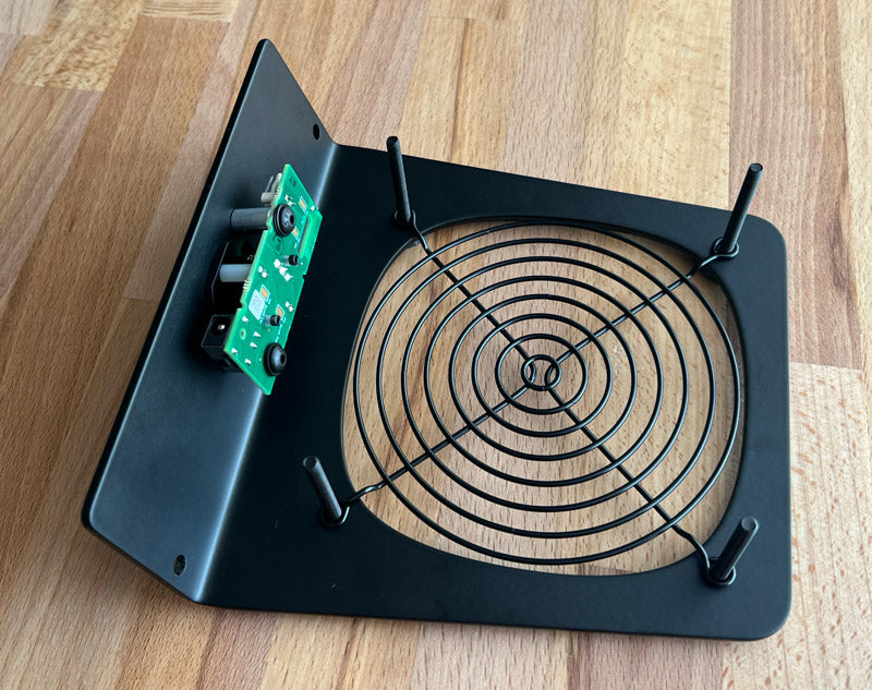
Unplug the fan wire connector from the speed control unit connector. Take note of the fan connector’s position before unplugging to help with reassembly. When unplugging the connectors, there’s a snap latch that will need to be pulled up to allow the fan connector to unplug. Do not touch the speed control unit other than the plastic snap latch.
-
Remove the black metal fan screen. Take note of the screen’s orientation to help with reassembly.
-
Remove the foam gasket.
-
Remove the fan wire and fan. Take note of the fan’s orientation to help with reassembly.
-
Remove the gasket and screen if needed for cleaning or other purpose. Take note of the screen’s orientation to help with reassembly.
-
Flip the metal support over.
-
Remove the four fasteners and Mac Mini supports if needed. -
Place the top metal support on the corner of a wood table. Feed one of the four #8-32 x 1 3/4” fasteners through the top of the Mac Mini supports and into the fastener head pocket within the non-slip pad. Thread the fastener into and through the top of the metal support, using the open area below the desk corner for the fastener. Thread the fastener all of the way to the bottom, but do not tighten and leave the fastener slightly loose.
-
Thread a second fastener and Mac Mini support into the other side of the metal support. Thread the fastener all of the way to the bottom, but do not tighten and leave the fastener slightly loose.
-
Thread the remaining fasteners into the metal support. Thread the fastener all of the way to the bottom, but do not tighten and leave the fastener slightly loose.
-
Flip the metal support over onto the pads.
-
Feed one of the black metal finger guard through the four fasteners. Note that the guard extends outward, and orientate the guard so that it extends downward in order to move the guard further from the fan for reduced noise.
-
Feed one of the foam gaskets through the four fasteners. Adjust the gasket so that it lays flat, is free of distortions and aligns with the plastic enclosure’s air opening below.
-
Feed the fan through the four fasteners. Orientate the fan so that the fan’s intake side is facing up and exhaust side is facing down (the fan’s exhaust side includes fan blade motor mounting and support frame). Rotate the fan so that the SVALT logo would be orientated upright and the fan wire would exit at the lower left corner when the cooling unit assembly is complete and installed onto the cooling stand. Leave the fan wiring to hang freely.
-
Feed the second foam gaskets through the four fasteners. Adjust the gasket so that it lays flat, is free of distortions and is centered on the fan below.
-
Feed the second black metal finger guard through the four fasteners. Note that the guard extends outward, and orientate the guard so that it extends upward in order to move the guard further from the fan for reduced noise.
-
Wrap the fan wire around the side, back and side of the fan, and then attach the fan connector to the speed control system’s fan connector.
-
Orientate the fan connector so that the rails align and then insert the two connector prongs into the upper two holes on the fan connector. Note that if the fan does not power up after assembly, then it is likely that the connector was inserted into the incorrect holes on the fan connector.
-
Fit the wide end of the plastic enclosure over the narrower end of the metal support and fan assembly. Tuck the fan wiring into the recessed corners of the fan frame.
-
Slide the plastic enclosure into place while keeping the fan wiring wiring within the fan's recessed corners.
-
There are three options for this step, depending on which of the following you prefer: install the dust filter frame and dust filter, install only the dust filter frame, or install neither the dust filter or frame.
- Dust filter and frame: Align the dust filter holes with the fasteners, then place the dust filter frame over the filter.
- Dust filter frame only: Align the dust filter frame holes with the fasteners.
- Neither filter nor frame: Proceed to the next step.
-
Press down a corner of the plastic enclosure (or on the dust filter/frame positioned above the enclosure) to expose the end of the fastener. Feed one of the finger tightening nuts onto the fastener end. Only thread the nut on to the point that the nut will stay attached, do not tighten. Make sure to feed the metal side of the nut onto the fastener ends and only apply light pressure onto the nut to avoid damaging the aluminum nut threads.
-
Repeat for the remaining three nuts.
-

Adjust the bottom gasket. Inspect the gasket to see if any portion is extending into the fan opening. Use the end of the hex key or other tool to push the gasket into place as needed.
-

Flip the cooling unit over, and then inspect and adjust the top gasket as needed.
-
Tighten the top fasteners. Start with one fastener and then move to the next in a clockwise direction.
-
Tighten the bottom finger tightening nuts. Start with one nut and then move to the next in a clockwise direction.
-

Tighten the nuts so that the rim edge of the plastic enclosure meets the metal support enclosure. The the metal support and plastic enclosure do not require a tight fit, so do not over tighten.
-
Plug the power supply into the fully assembled cooling unit (do not plug into a partially or incorrectly assembled cooling unit), and cycle through the fan speeds. If the fan does not turn on, then the fan connector may need to be repositioned as noted above in step number 11.
Cooling Dock Dx / DLx / D1 Pro / D1 Legacy / D1:
Cooling System Removal Guide


Cooling Dock Dx / DLx / D1 Pro / D1 Legacy / D1:
Cooling System Installation Guide


Cooling Dock Dx / DLx:
Fan Removal Guide


Cooling Dock Dx / DLx:
Fan Installation Guide


Cooling Dock D2n Pro / D2 Pro / D2 Legacy / D2:
Cooling System Removal Guide


Cooling Dock D2n Pro / D2 Pro / D1 Legacy / D2:
Cooling System Installation Guide


Cooling Dock DHCx:
Fan Removal Guide


Cooling Dock DHCx:
Fan Installation Guide


Cooling Fan Fx:
Fan Removal Guide


Cooling Fan Fx:
Fan Installation Guide


Cooling Stand all models
(SRx / Sx / S Pro / SRxM / SxM / S Mini):
Cooling System Removal Guide


Cooling Stand all models
(SRx / Sx / S Pro / SRxM / SxM / S Mini):
Cooling System Installation Guide


Cooling Stand SRx / Sx / S Pro:
Fan Removal Guide


Cooling Stand SRx / Sx / S Pro:
Fan Installation Guide


Cooling Stand SRxM / SxM / S Mini:
Fan Removal Guide


Cooling Stand SRxM / SxM / S Mini:
Fan Installation Guide


All Models:
Dust Cleaning Guide
An air blower such as the Giottos Large Rocket Air Blower is recommended for removing dust. The blower can be used to remove dust without product disassembly, but if a more thorough cleaning is required, then disassembly may be helpful. Note that when cleaning the fan, you might want to blow out dust that may have accumulated in the open gap between the fan frame and fan blades, where the fan motor is exposed to dust accumulation.
Back to top
All Models:
Surface Finish Cleaning Guide
Anodized Aluminum SurfacesFor anodized aluminum surfaces, blow dust out of cooling fin air channels and other hard to reach areas. Once dust and debris are removed, then use a cloth dampened with soapy water to clean surfaces.
Metal and Powder Coated Metal Surfaces
For metal and powder coated metal surfaces, wipe the surface with a microfiber cloth.
Thermally Conductive Assembly Surfaces
For the yellow-orange thermally conductive interface, use a white non-dyed microfiber cloth to clean the surface, do not use a colored cloth as it will stain the surface. If additional cleaning is required, then dampened a portion of the microfiber cloth with water, soapy water or 70% isopropyl alcohol. Do not allow any moisture to get near edges where it could contact and potentially damage adhesives. Once clean, then polish surface with a dry portion of the microfiber cloth.
Plastic Type Surfaces
For plastic and plastic type surfaces, take care when cleaning as the surface can be scratch. Use a soft cloth with light pressure to clean. Slightly dampened cloth with soapy water as required to aid cleaning. Avoid exposing adhesives and electronics to moisture.
Rubber Type Surfaces
For rubber and rubber type surface, simply brush off the surface.
Back to top